Advanced Visualization: Working with Annotations
This short protocol reviews how to add an manipulate annotations in Cytoscape.

Annotations in Cytoscape
Cytoscape has three separate drawing surfaces on which the network and annotations are drawn:
- Network canvas: where nodes and edges are drawn.
- Background canvas: the drawing surface behind nodes and edges.
- Foreground canvas: the drawing surface in front of nodes and edges.
Annotations are drawn either on the foreground or background canvases, and are exported as objects. They are high quality graphically, allowing for export of images. Annotation types:
- Shapes, Text, Bounded Text, Images and Arrows
- Groups, to group annotations together
Annotation Panel
The
- To start, navigate to the
Network Search at the top of theNetwork Panel , and selectNDEx in the drop-down. - Type in galFiltered and click the search icon. In the results, select the galFiltered.sif - STE12 subnetwork network and click the green arrow to open in Cytoscape.
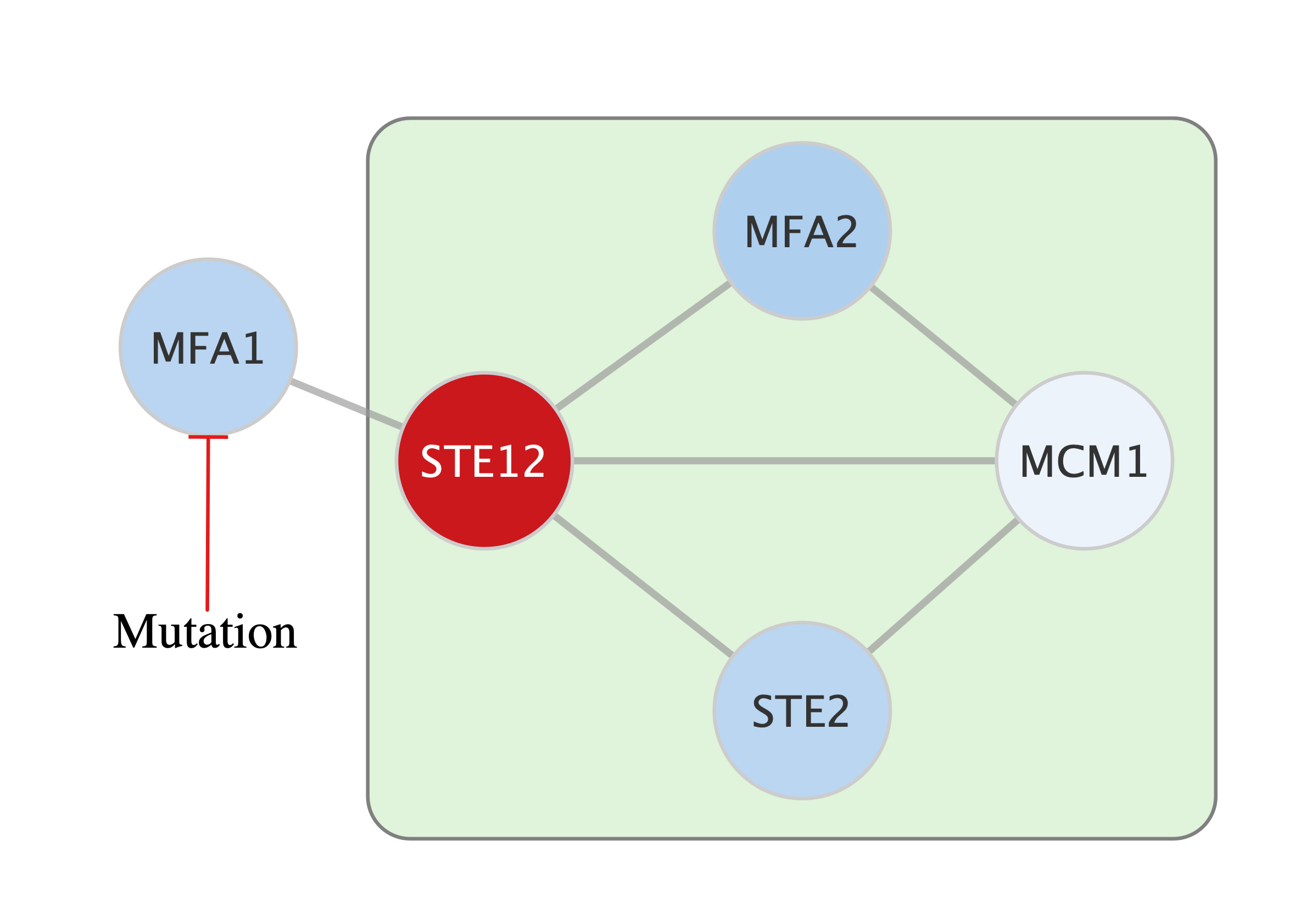
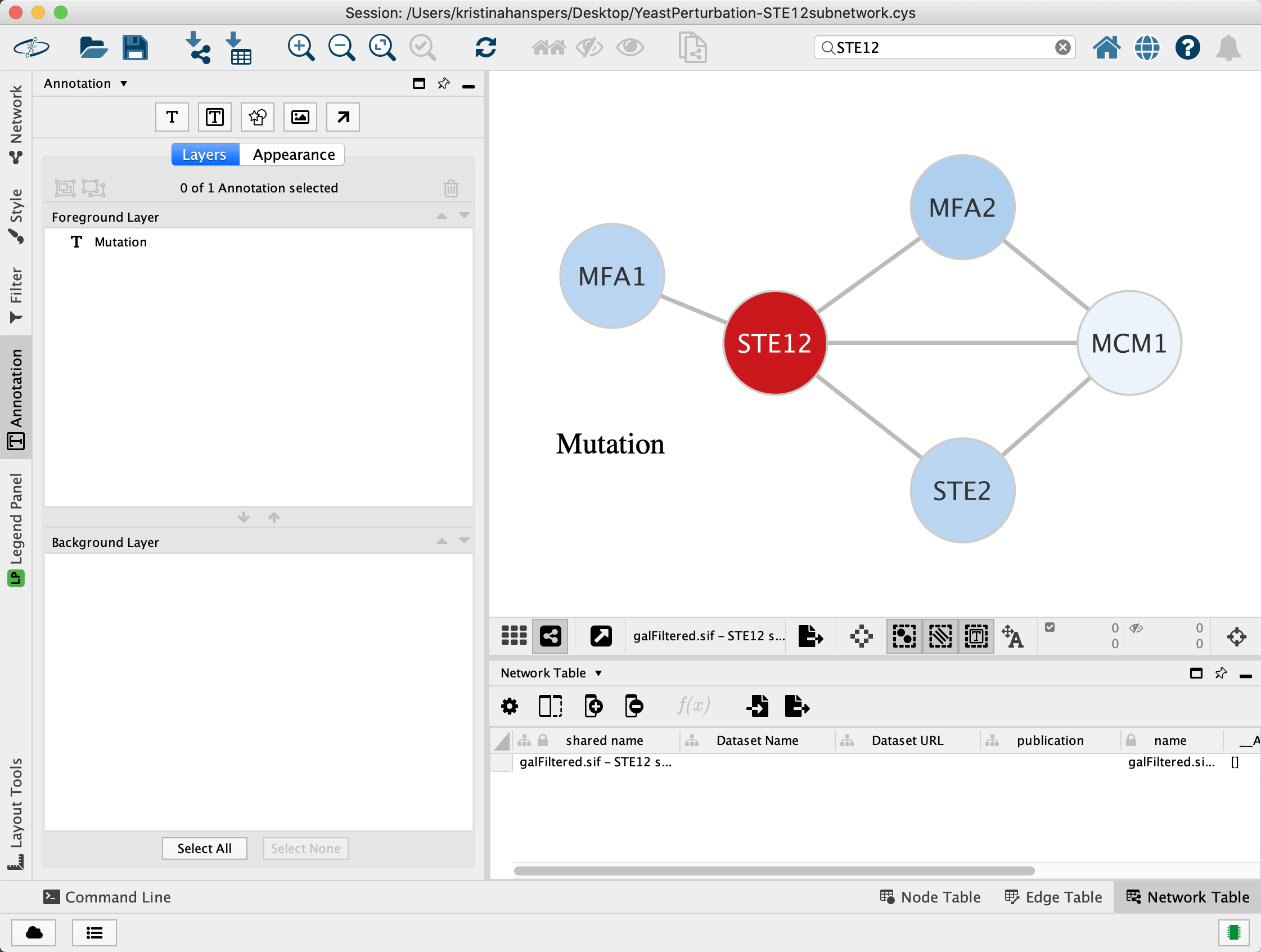
Adding a Label Annotation
- To add a label annotation, click the
Text button at the top of theAnnotation panel. - Click anywhere on the canvas to place the label, and in the
Appearance interface, enter the desired label and select font and color. - To adjust the location of the annotation, first click the
Toggle Annotation Selection  . The annotation can now be moved by click and drag.
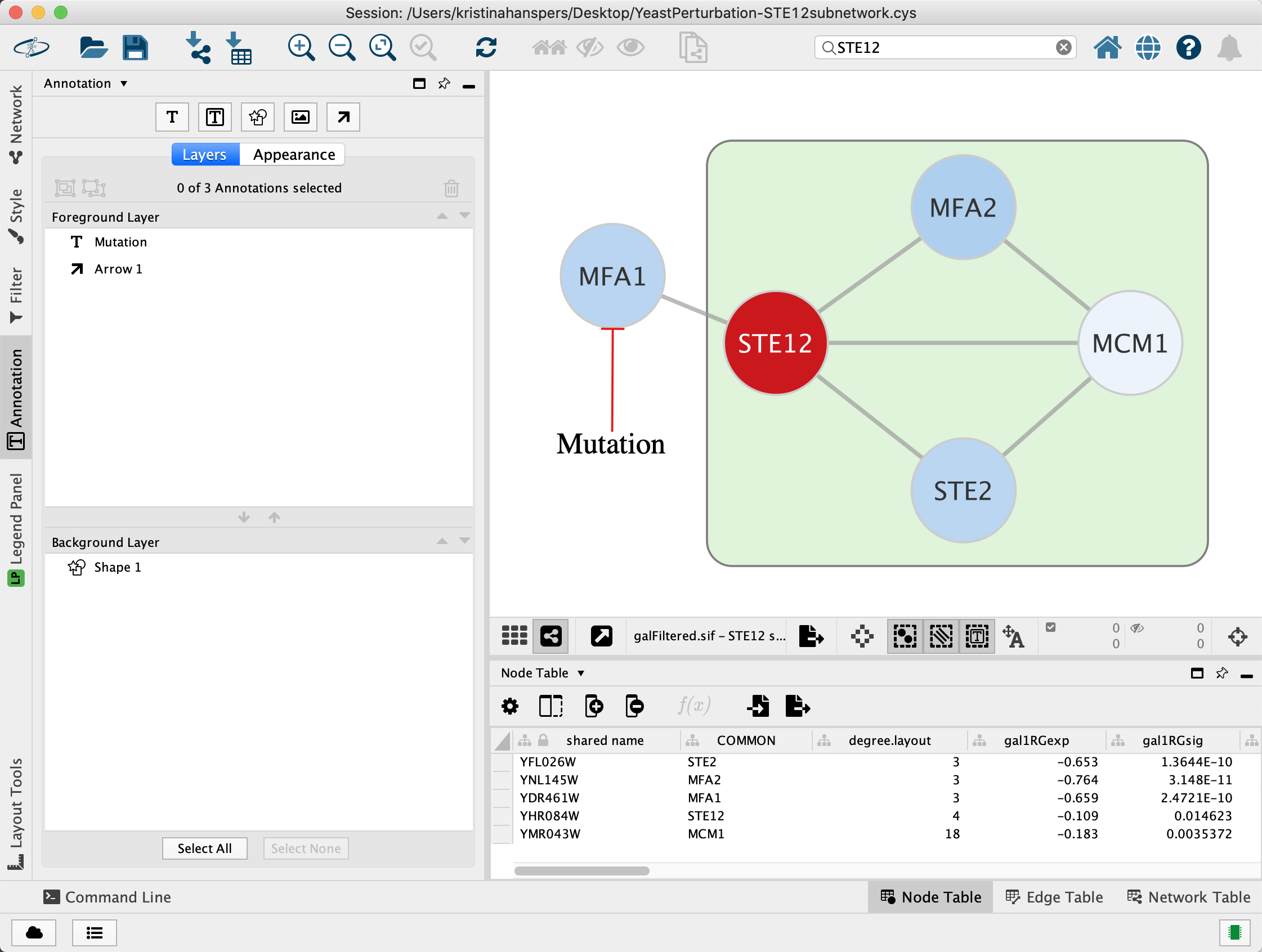
Adding an Arrow Annotation
- To add an arrow annotation, click the
Arrow button at the top of theAnnotation panel. - Instead of clicking on the canvas, first click the annotation you want the arrow to point from, in this case the label added previously.
- Next, click on the node or annotation you want to point the arrow to.
- In the
Appearance tab of theAnnotations Panel , select line color and arrow style and color. In this case, we will add a red line with a red t-bar end.
Adding a Shape Annotation
- To add a shape annotation, click the
Shape button at the top of theAnnotation panel. - Click anywhere on the canvas to place the shape, and in the
Appearance interface, select the desired shape, color etc. - The new shape will automatically be selected, and you can now size it to your liking and then click on the canvas to set the size.
- By default the shape will be drawn on the foreground canvas, obstructing any nodes behind it. To move it to the background canvas, select the shape in the
Layers tab in theAnnotation panel and click thePush Annotations to Background Layer arrow just below the list.
Editing Annotations
When the button is enabled, annotations can be selected and edited.
- Click on an annotation to bring activate the
Appearance panel. - To delete one or more annotations, select them in the
Annotations Panel and click the delete button at the top. Alternatively, select them in the network and clickDelete on the keyboard. - As was described previously, annotations can also be moved between the background and foreground layer in the
Layers tab in theAnnotations Panel .
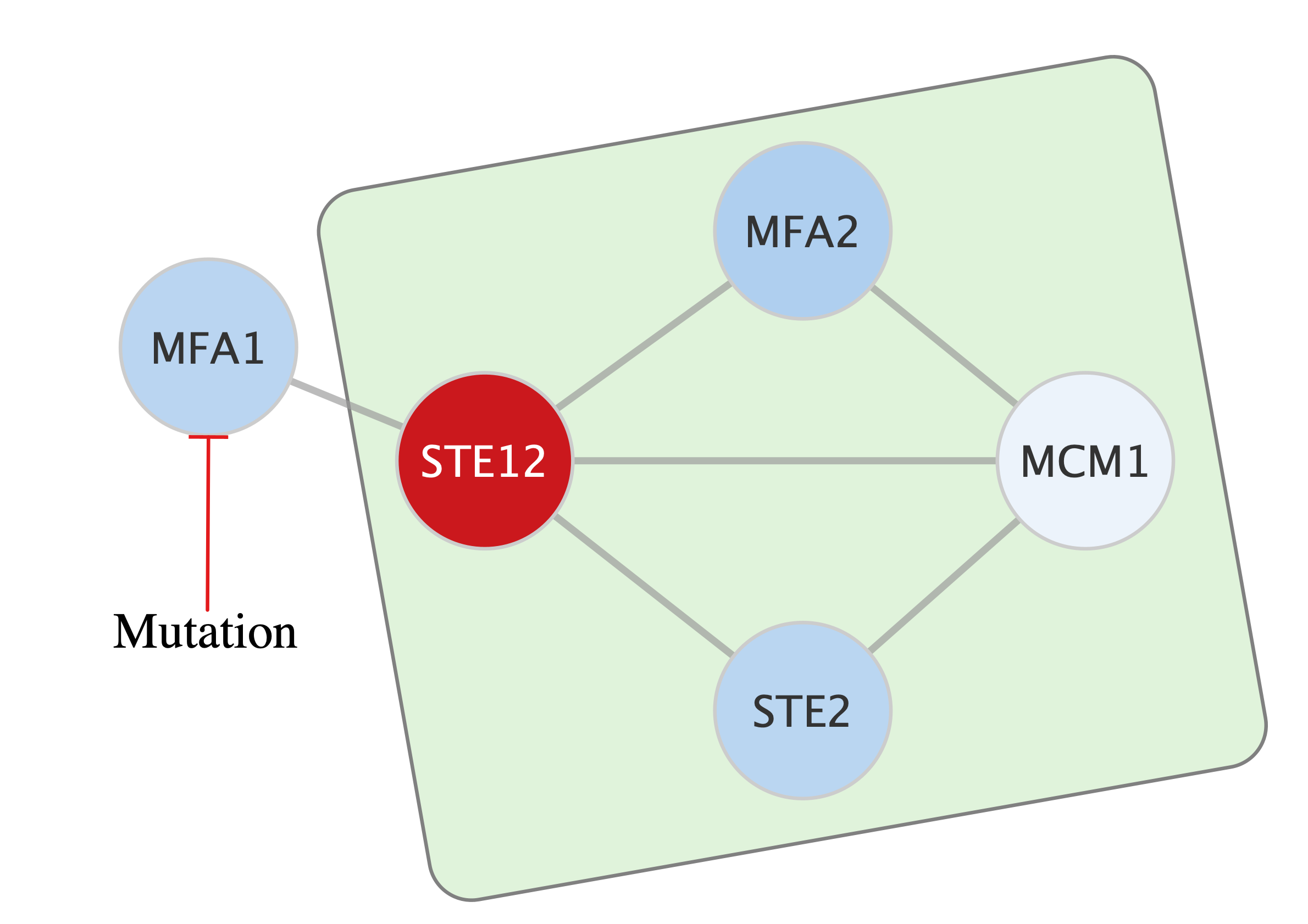
Rotating Annotations
Annotations can also be rotated:
- Select the shape annotation we added earlier.
- In the
Appearance panel, drag theRotation Angle to about -20. This will rotate the object 20 degrees counter-clockwise.
For more information on using annotations in network visualization, see the Ten Simple Rules protocol.